Here Are Some of Our Project Specifications
CAI Representatives are available for a FREE consultation. Please call (800) 622-1314 or click here to email us.
Trinitas Medical Center Roof Rehabilitation/ Restoration Project, Elizabeth, NJ
The Medical Center project scope of work consisted of rehabilitating & restoring the roof system & the exterior of the elevator penthouse. The North Tower building is approximately 133,000 SF and 120+ feet tall. The Hospital Building sits in north side of the campus in Elizabeth New Jersey for almost 60 years. Now newly restored, being an icon for the city, located two blocks from the town business center & Union County Court House, 6 blocks from the train station approx. 1 mile west of the US RT. 1 & 9 & 3 miles from NJ Turnpike Exit 13 in Northern New Jersey.
The original building was constructed in the 1950s with a (BUR) Built-up roof system. The rehabilitation work was for the later installed roof system constructed with EPDM single-ply membrane adhered to 1 1/2” Polyicanurate insulation system adhered to concrete deck below. With past high wind conditions, the roof system had lifted & pulled away from the deck and failed due too improper adhesion of the Polyicanurate insulation to concrete deck below & improperly installed roof drains were the main factors causing the failure and leaks to the roof system.
The elevator penthouse brick masonry was cracked in several areas also, had many open mortar joints with missing mortar, peeling paint, cracked, delaminating, and spalled bricks.
The code requirements for a high rise building roof system must be fully adhered or mechanically attached to the roof deck.
The challenges for the project were many to overcome, IE: Hospital Environment, Working Conditions, Safety & Noise control for the patient, & Safety for the workers on the project & Logistics to execute the work.
Hospital Environment, Roof leaks had to be minimized during construction, especially to the patient areas. A cut and replace method of the old roof areas making each work section watertight with a temporary seal by end of each work shift on a daily basis would be required to maintain water tightness during construction.
Working conditions: Dust control & Cleanliness, Precautions were taken to control dust entering the hospital areas during transport of materials & equipment IE: dust barriers, tack pads @ entrances & doorways, elevators, stair towers, hallways & doors to roofs, transporting materials in covered condoles while traveling through the service elevators & service corridors & etc. was necessary.
Safety & Noise control for the patients: Safety was paramount to make the worksite safe & quiet for the patients, doctors, hospital staff, and guests. Certain work had to be done on off-hours to accommodate the patients & staff. Special hoisting towers were installed to hoist the materials and equipment to the upper work levels of the roofs.
Safety for the workers on the project: Hard hats, eye, ear & respiratory protection were provided to the workmen. Full-body harnesses for the workers with lanyards and safety rope tie-offs for the hazard areas of the roof project.
Logistics: The logistics for the actual production was even more challenging. There was little space for storage of materials & equipment inside the building & no space available outside the building. The storage inside was restricted to a 6’ x 20’ & 6’ x 15’ areas of the mechanical room amongst the building equipment. However, the freight elevator was limited to 8’L x 6’W x 8’H limited the material & for small equipment & short length materials. Material could be transported only to the mechanical penthouse level, which left the three upper floors with only roof steel ladders access to the roofs above.
The project was set up on a pre-engineered basis including the material fabrication. The roof layout performed with 2D & 3D CAD with Pictometry drawings, field measurements & drawings and digital photos. The layout was made like a picture puzzle for the entire building roof into predesigned layout of production sections. This is based on size, weight, width, & length of the membrane for deck sheets, taking into account the rooftop equipment, bump-outs, penetration, handling sizes & obstructions, included for the flashing sheets, parapet sheets, coping sheets, and their prospective place. Then the shop drawings are approved by the Project Managers for release of the materials for fabrication. The membrane material consisted of 40 mill thick sheets with fastening tabs attached to rear side every 3 LF for attaching to the deck below.
HPPM (High Performance/Protection Membranes) Services sm (for Minimizing Excess Moisture Mold & Keeping a Dryer & Safer Building Interior) The World’s Best Roof.
CAI’s Cool Roof Technology & (VAE) Value Added Engineering services is a pioneer & leader in reflectivity and cool roofing In the commercial & industrial roofing industry.
In the roofing industry reflectivity and cool roofing has been the dominant discussion point for several years. One of CAI’s suppliers, Duro-Last® Cool Zone® roofing system, has set the standard for single-ply roof reflectivity and the resulting energy savings. Now, terms like sustainability, cool roofs, and cool roofing are receiving a lot of attention and once again, Duro-Last is setting the bar.
What do sustainability and cool roofing really mean for building owners, facility managers, contractors, architects, and other specifiers? It means that the design, construction, maintenance, life-cycle impact, adaptive reuse, destruction and recycling of roofing components must help meet the long-term environmental standards demanded by today's high-performance buildings.
To be considered "sustainable," a roofing system must meet the Five E's of high-performance roofing: Energy, Environment, Endurance, Economics, and Engineering. In each of these areas, the Duro-Last Cool Zone roofing system leads the commercial roofing industry. Click on the Five E's link above to learn more about the Five E's and how the Duro-Last Cool Zone roofing system delivers on the multiple demands of high-performance roofing.
Learn more about the Five E's:

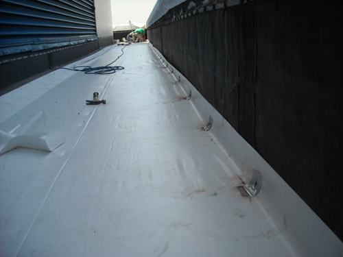
The membrane materials are custom prefabricated for the job and conform to the shop drawings, manufactures’ specifications, and installation requirements. Upon completion of the sub straight and base preparation, the fabricated membrane and accessory materials have already arrived at the jobsite waiting to be installed on the prepared roof deck system.
All roof system materials were mechanically fastened (drilled & screwed to the concrete deck, masonry parapets walls & finally the limestone coping)
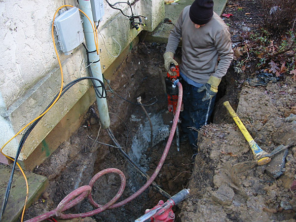
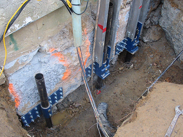
To do all of this timely and economically CAI had performed (VAE) Value Added Engineering services for the project. The VAE services included a thorough investigation of not only the roof system. It also included the masonry parapets & coping, masonry & concrete walls, and wall penetrations. CAI developed and incorporated a tailored rehabilitation system of the deck roofing components, parapet, & coping waterproofing components. A pre-engineered roof membrane system including exterior masonry wall waterproofing and restoration repair work.
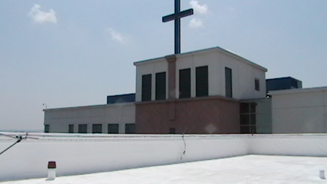
CAI was originally called into this project to investigate these issues in the summer of 2010. After the bidding/proposal process, CAI was awarded the project and work started in March 2011 with successfully completing the project as per schedule. Trinitas has been a CAI customer since 1992.
REQUEST A QUOTE
Fields with (*) are required.
Structural Rehabilitation of Ventilation System Project for the Holland Tunnel
The Holland Tunnel Architectural & Structural Rehabilitation of Ventilation Buildings Project. One is situated in the Hudson River and the other on land at Riverside South in Jersey City, NJ. The newly restored buildings are an icon for the city. Located in the business center of Jersey City. 6 blocks from the Holland Tunnel entrance. 1 mile east of the US RT. 1 & 9 and NJ Turnpike Exit 14C. 2 miles east of New York City in Northern New Jersey.
CAI Restoration undertook a complex custom rehabilitation operation for the building envelope restoration and interior concrete repair of the Holland Tunnel Architectural & Structural Rehabilitation project located in Jersey City, NJ. The work on the Holland Tunnel ventilation buildings had difficult challenges to overcome while meeting stringent requirements and unique situational challenges. Chief among the concerns of the rehabilitation project were the need to keep the ventilation system operational throughout the duration of the project since the tunnel and the ventilation system in the buildings can never stop. It must operate on a 24/7/365 schedule for the safety of the employees working in the tunnel and the occupants in the vehicles driving through the tunnel. As part of this, it was important to carry out selective demolition processes safely, precisely, and delicately with minimal dust entering the intake fans. In addition, due to the need for subsequent trades work that follow, keeping to a tight time schedule was very paramount.
Selective demolition was carried out on exterior and interior of the ventilation building structures: Exterior brick masonry (with triple width walls and triple width reinforcement. Creating volume fourfold over today’s masonry standards), structural concrete, limestone façade panels (these at fivefold volume over today’s standards), coping stone, and cornice natural stone. In order not to disturb adjacent finishes, utilities, electrical and critical air moving equipment. We designed a high production breaking/removal system, featuring specially fabricated concrete breakers and cutting edges varying in size from handheld and 15 lbs.-25 lbs. range, to portable suspended breakers with 35 lbs.- 90 lbs. in breaking weight force.
This enabled us to efficiently saw the isolated demolition areas for the brick facade which were then jackhammered out, brought to roll-off containers 150 ft. below the building and recycled. The NJLB brick masonry demolition created approximately 14,687 cubic feet of rubble, (955 tons) and the NJRB brick masonry demolition created approximately 14.316 cubic feet of rubble (930 tons), the limestone façade with backup. Demolition created approximately 5,068 cubic feet of rubble (329 tons). Approximately 179,000 units of new brick were installed with additional 5200 SF brick tuckpointing work done on other brick masonry conforming to ACI 530.1/ASCE 6 standards.
Similar restoration work was carried out on the concrete and limestone portions of the building, via cutting, chip hammering and in the case of cracked limestone, developing an onsite fabrication shop for repairs, refacing, retooling and gluing. Saving time, cost and satisfying green reuse initiative. We also carried out repair processes including rebar/steel wire reinforcement, resetting panels, injection of super-high strength concrete repair mix and tuckpointing of defective joints. In addition, CAI carried out all rigging, gantry, anchoring, scaffolding, and chaining requirements.
Altogether, this structural rehabilitation process consisted of 27,516 sq. ft. of brick, 9,225 sq. ft. of concrete removal and repair. 4,608 SF of limestone removal and replacement. 5,826 sq. ft. of limestone repair. An inspector and project architect supervised the process and ACI, ASCE, IMI, and ASTM standards were met in process and materials used. For more information on our rehabilitation and rebuilding capabilities please contact CAI today.
In summation the following CAI services applied to the Holland Tunnel Project:
- BER&R (Building Envelope Rehabilitation & Restoration) Services sm (for Better Building Operation, Safety and Comfort, of the Employees & Occupants)
- HPPM (High Performance /Protection Membranes) Services sm (for Minimizing Excess Moisture Mold & Keeping a Dryer & Safer Building Interior)
- EWR&R (Exterior Wall Rehabilitation & Restoration) Services sm (for a more Aesthetically Appealing Facade Exterior)
- MCSR&R (Masonry, Concrete & Stone Rehabilitation & Restoration) Services sm (for Minimizing Water Seepage & Maintaining Structural Integrity and Appealing Facade Exterior)
BRIEF HISTORY - Holland Tunnel
The Holland Tunnel was opened in 1927. The tunnel ventilation system design was what made the Holland Tunnel feasible in the first place, due to the tunnel’s enormous length. The exhaust fumes from the vehicles were a major challenge to overcome. In 1919 the joint NY & NJ Bridge & Tunnel Coalition finally decided on building a tunnel with a twin-tube design. Selecting a pioneering design by an engineer named Clifford Holland was selected, then later bore his name. He and his team designed a very sophisticated mechanical ventilation system with a revolutionary two duct system. One duct to draw the fresh air in and the other to suck out the fumes. This air is moved by 42 blowing fans and 42 exhaust fans - totaling 6,000 horsepower - arranged in four ventilation buildings, for its time in history. His design made the tunnel possible to be built. Prior to construction the team tested vehicles within closed chambers. Then volunteer occupants in their cars tested to determine the effect of the fumes. The team determined that air with only one-half percent carbon monoxide might be lethal. It takes approximately 90 seconds to completely change the air in the tunnel.
REQUEST A QUOTE
Fields with (*) are required.
Kingswood Station Condominiums Stabilization Project - East Brunswick, New Jersey
The Kingswood Underpinning & Stabilization Project is a large Residential Condominiums, Townhouse Community in East Brunswick, Middlesex County, New Jersey, located in the north central part of the state. It was originally a previously abandoned farm & vacant land project.
Building 208-211 and several other units were built on unsuitable soils & fill that have experienced similar settlement issues.
Shortly after completion these buildings were experiencing settlement, cracking of drywall & exterior stucco wall finishes, doors not shutting or jamming up when opening, windows not opening and or sticking and jamming on opening & closing. Then later the problem got worse. There were visible cracks in the concrete Cablevision Stabilization Projects, sinking sidewalk slabs and sinkholes in flowerbeds near Cablevision Stabilization Project walls.
The owner’s representative had local contractors make the repairs. However, the situation of the settling worsened. It eventually was slanting the floors. They were uneven and leaning furniture towards walls. Also, uneven floors at dissimilar floor finishes, in the kitchen and bathroom areas.
There were two unsuccessful attempts by an engineer and two contractors to shore up and stabilize the Town House Building. The owner’s representatives then called CAI Restoration Services in to survey and evaluate the problem at the Townhouse site.
In the winter of 2005 CAI started the work to rehabilitate and stabilize the existing concrete/ masonry Cablevision Stabilization Project by installing the underpinning system to shore up and stabilize the structure and protect it from future settlement.
CAI designed and specified a (Push Pier Piling System) PPPS. CAI furnished and installed the pre-engineered underpinning as manufactured by Magnum Piering Company.
This Piering system is similar to Micropiles but without all the drilling noise, dust, big and noisy air compressors, messy grout mixing, pumping and filling of the Micropiles and the curing time required before loading the Micropiles piles. However, the Micropiles would make a big mess that required a large crew to clean up that add additional costs to the project owner.
The PPPS (Push Pier Pile System) CAN BE LOADED up immediately upon completion of the Pier driving. The PPPS, (Push Pier Pile System) performs a Full-Scale Load Test with Each Installed Pier. When a Magnum push pier is installed to refusal, a full-scale load test is being conducted on the system components being installed.
Furthermore, the buildings were all occupied. If we had used the Micropiles the dust, noise and grout mess would have been big inconveniences to the tenants in the units, not including the addition costs to the project owner.
The Magnum Steel Push Pier System is very quiet, clean and ready to go upon completion of the Pier driving. No waiting time for curing of grout, and returning a second time for final connection & loading them to the building.
The Magnum Steel Push Pier System is a pre-engineered system designed and supported by engineers who understand the complexities of soil mechanics and structural load support requirements.
The stabilization work consisted of installing the Piers at strategically laid out positions to meet the settled and cracked Cablevision Stabilization Project areas, but also to clear and support the entrances & wide span window openings to the building and at the same time maintain the building load forces equalized spans.
The Pier installation started at the front corner of the building with a Test Pier. After the Test Pier was installed and tested, it was inspected by the engineer. The design load premeasures verified and approved by the engineer. The installation continued from the front corner of the building along the side to the rear corner & continuing around the rear, finishing at the front porch of the building. Due to the site conditions, IE: The clayey soil conditions, possibility of buried obstructions, debris and rubble. CAI along with the engineer had approved the Magnum PPPS (Push Pier Pile System). Piering System with the Magnum Piering patented friction-reducing rings to drive the Piers through clayey soils with minimum restriction to achieve design loading pressures as the underpinning system for the Project. The Magnum Piering System consisted of 34 Magnum PPPS (Push Pier Pile System) with patented friction-reducing rings on lead anchor to be driving 24’LF to 45’ LF deep to the suitable soils stratum below.
By connecting the existing footings to The PPPS (Push Pier Pile System) with the special heavy-duty steel brackets thus transferring the load of each steel column from the existing concrete footing to the HD steel bracket to the PPPS (Push Pier Pile System) down through the unsuitable soils to the suitable soil stratum/rock below without the need for all the drilling noise, dust, big and noisy air compressors, messy grout mixing, pumping , filling of the Micropiles , curing lag time, expensive heavy equipment, excavation, drilling, concrete grouting, major cleanup restoring work that was required in the option above.
We accomplished all of this work within 18 days with minimal inconvenience to the occupants of the building with minimal disturbance to the property site, adjacent buildings and neighbors in the community complex.
REQUEST A QUOTE
Fields with (*) are required.
Cablevision Stabilization Project - Paterson, New Jersey
The Cablevision Stabilization Project was a re-development project from a previously abandoned project that was purchased from the City of Paterson by Dornoch Holdings, LLC. The project is in the City of Paterson on 75-81 Ellison St. just down the block from Lou Costello Memorial Park (Renowned Comedian), located in Northern New Jersey.
When the project was being constructed it was discovered by the contractor while excavating of the elevator shaft pit they encountered demolition debris. After further excavating and probing it was determined the debris was probably from the prior structure on the site. It was a possibility that the rest of existing pier footings was also constructed over unsuitable soils IE: demolition debris, cobblestones, broken bricks, masonry debris, etc. The project architect was then advised of the problem. A soil engineer was called in to inspect and he did additional testing and verified the situation of the unsubtle soil conditions of the site. The soil would not support the design loads of the proposed new building.
At this point all work at the site was stopped and the owner had to get hard answers on how to correct the problem. He then needed to make some tough decisions on how to pay for this cost overrun to correct the unsubtle soil issues.
This delay was costing him dearly since the CM, GC and subcontractors were contracted and working on the project. The materials & equipment was ordered and the project was in full swing until it came to an abrupt stop. Nothing was moving forward and the costs continuing & mounting. The owner needed solutions with the least cost and fastest turnaround to get the project moving again.
One of the options was to take down the existing structure, including removing the entire existing Cablevision Stabilization Project. Excavate the entire fill below down to the suitable substrates and then place the new Cablevision Stabilization Project on the suitable strata approximately fifteen to eighteen feet below the existing grade.
This mass excavation work required installing temporary steel sheet piling on four sides of the building because two sides were very close to an existing 10 story buildings. It also required removing the entire sidewalk on the Ellison Street side, relocating utilities and temporally closing Ellison Street (which would require special planning board approval). When the new Cablevision Stabilization Project work was completed restoring the backfilling of the sidewalk excavation, removing sheeting, restoring the utilities, curbs, pavement and street. However, this option was adding about 60% to 80% more cost to the project and just too expensive and not economically feasible for the project to proceed.
In 2006 CAI was called in to rehabilitate and to stabilize the existing concrete/ masonry Cablevision Stabilization Project by installing the underpinning system to stabilize the structure and protect it from future settlement.
The engineer then had suggested an alternative design to the mass excavation. CAI with the engineer’s approval designed a very economical underpinning system for the column footings and building Cablevision Stabilization Project utilizing Helical Piling, the Piling/Piers to support the total structure. By connecting the existing footings to the helical piers with special heavy-duty steel brackets thus transferring the load of each steel column from the existing concrete footing to the HD steel bracket to the Helical Piling/ Piers (also known as screw piles) down through the rubble to the suitable soil stratum below without the need for the expensive mass excavation and restoring work that was required in the option above.
Due to the site conditions, IE: The buried demolition debris and rubble. CAI along with the engineer had approved the Magnum Helix Piering System, (Helical Piling) with the Magnum Piering, with patented dual cutting blades as the underpinning system for the Project. The Magnum Piering System consisted of 134 Magnum Helix Piers with dual cutting blades on 8” 10” and 12” helices on lead anchor, and with dual cutting blades on 12” and 14” helices second lead anchor and with 2 ea. - 6’ extensions to achieve a total design depth of 24 ‘below existing footings through the rubble into the sandy soils stratum below.
The design included 119 Magnum heavy duty steel L brackets, 8 straight steel brackets, 8 concrete grade beam pile caps, 1,400 ea. 1/2”x8” concrete anchors for the connections to the existing concrete footings.
CAI also encountered concrete that was below standard requirements in design strength. CAI”s Value-added engineering (VAE) for the design, fabricate, Installation of the alternate anchoring system for the weak concrete and specified 200 ½”+1”x 12” SS epoxy anchors that were needed for effectively connecting steel brackets to the existing concrete that was below standard requirements strength. Because the standard concrete anchors failed during installation. They were not holding in the existing weak concrete footings.
REQUEST A QUOTE
Fields with (*) are required.